Version: 8.3.0
Basic 1D hypothesis specifies:
1D hypotheses can be categorized by type of nodes distribution as follows:
Adaptive hypothesis allows to split edges into segments with a length that depends on the curvature of edges and faces and is limited by Min. Size and Max Size. The length of a segment also depends on the lengths of adjacent segments (that can't differ more than twice) and on the distance to close geometrical entities (edges and faces) to avoid creation of narrow 2D elements.
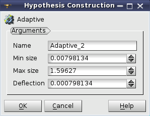
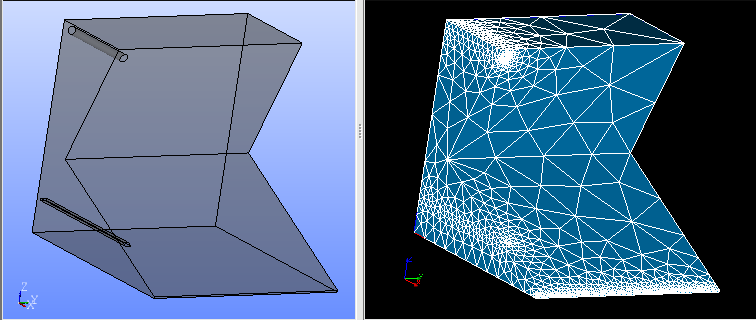
See Also a sample TUI Script that uses Adaptive hypothesis.
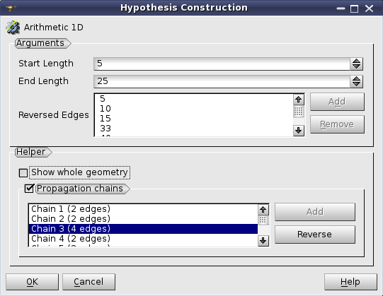
Arithmetic Progression hypothesis allows to split edges into segments with a length that changes in arithmetic progression (Lk = Lk-1 + d) beginning from a given starting length and up to a given end length.
The splitting direction is defined by the orientation of the underlying geometrical edge. Reverse Edges list box allows specifying the edges, for which the splitting should be made in the direction opposite to their orientation. This list box is usable only if a geometry object is selected for meshing. In this case it is possible to select edges to be reversed either directly picking them in the 3D viewer or by selecting the edges or groups of edges in the Object Browser. Use Add button to add the selected edges to the list.
Helper group assists you in defining Reversed Edges parameter.
See Also a sample TUI Script of a Defining Arithmetic Progression and Geometric Progression hypothesis operation.
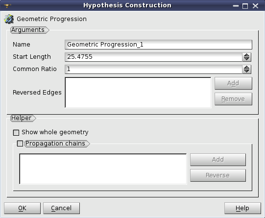
Geometric Progression hypothesis allows splitting edges into segments with a length that changes in geometric progression (Lk = Lk-1 * d) starting from a given Start Length and with a given Common Ratio.
The splitting direction is defined by the orientation of the underlying geometrical edge. Reverse Edges list box allows specifying the edges, for which the splitting should be made in the direction opposite to their orientation. This list box is usable only if a geometry object is selected for meshing. In this case it is possible to select edges to be reversed either directly picking them in the 3D viewer or by selecting the edges or groups of edges in the Object Browser. Use Add button to add the selected edges to the list.
Helper group assists you in defining Reversed Edges parameter.
See Also a sample TUI Script of a Defining Arithmetic Progression and Geometric Progression hypothesis operation.
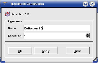
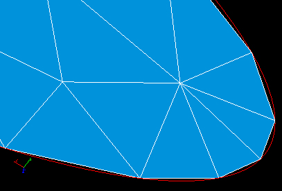
Deflection hypothesis can be applied for meshing curvilinear edges composing your geometrical object. It defines only one parameter: the value of deflection (or chord error).
A geometrical edge is divided into segments of length depending on edge curvature. The more curved the edge, the shorter the segment. Nodes on the edge are placed so that the maximum distance between the edge and a segment approximating a part of edge between two nodes should not exceed the value of deflection.
See Also a sample TUI Script of a Defining Deflection hypothesis operation.
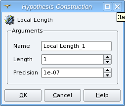
Local Length hypothesis can be applied for meshing of edges composing your geometrical object. Definition of this hypothesis consists of setting the length of segments, which will approximate these edges, and the precision of rounding.
The precision parameter is used to round a number of segments, calculated by dividing the edge length by the specified length of segment, to the higher integer if the remainder exceeds the precision and to the lower integer otherwise.
Use value 0.5 to provide rounding to the nearest integer, 1.0 for the lower integer, 0.0 for the higher integer. Default value is 1e-07.
For example: if edge length is 10.0 and the segment length is 3.0 then their division gives 10./3. = 3.33(3) and the remainder is 0.33(3). If precision is less than 0.33(3) then the edge is divided into 3 segments. If precision is more than 0.33(3) then the edge is divided into 4 segments.
See Also a sample TUI Script of a Defining Local Length hypothesis operation.
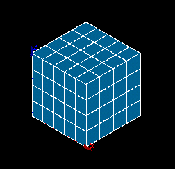
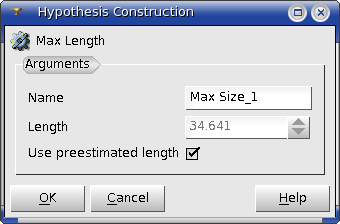
Max Size hypothesis allows splitting geometrical edges into segments not longer than the given length. Definition of this hypothesis consists of setting the maximal allowed length of segments. Use preestimated length check box lets you use length automatically calculated basing on size of your geometrical object, namely as diagonal of bounding box divided by ten. The divider can be changed via Ratio Bounding Box Diagonal / Max Size preference parameter. Use preestimated length check box is enabled only if the geometrical object has been selected before hypothesis definition.
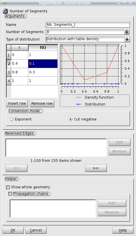
Number of Segments hypothesis can be applied for approximating edges by a definite number of mesh segments with length depending on the selected type of distribution of nodes. The default number of segments can be set via Automatic Parameters / Default Number of Segments preference parameter.
The direction of the splitting is defined by the orientation of the underlying geometrical edge. Reverse Edges list box allows to specify the edges for which the splitting should be made in the direction opposing to their orientation. This list box is enabled only if the geometry object is selected for the meshing. In this case it is possible to select edges to be reversed either by directly picking them in the 3D viewer or by selecting the edges or groups of edges in the Object Browser.
Helper group assists you in defining Reversed Edges parameter.
You can set the type of node distribution for this hypothesis in the Hypothesis Construction dialog bog :
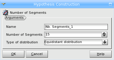
Equidistant Distribution - all segments will have the same length, you define only the Number of Segments.
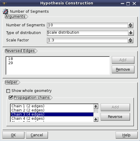
Scale Distribution - length of segments gradually changes depending on the Scale Factor, which is a ratio of the first segment length to the last segment length.
Length of segments changes in geometric progression with the common ratio (A) depending on the Scale Factor (S) and Number of Segments (N) as follows: A = S**(1/(N-1)). For an edge of length L, length of the first segment is L * (1 - A)/(1 - A**N).
Distribution with Analytic Density - you input the formula, which will rule the change of length of segments and the module shows in the plot the density function curve in red and the node distribution as blue crosses.
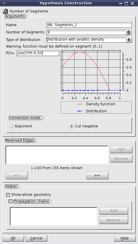
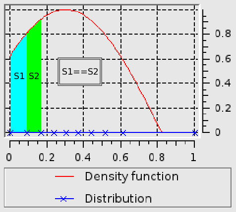
The node distribution is computed so that to have the density function integral on the range between two nodes equal for all segments.
Distribution with Table Density - you input a number of pairs t - F(t), where t ranges from 0 to 1, and the module computes the formula, which will rule the change of length of segments and shows in the plot the density function curve in red and the node distribution as blue crosses. The node distribution is computed in the same way as for Distribution with Analytic Density. You can select the Conversion mode from Exponent and Cut negative.
See Also a sample TUI Script of a Defining Number of Segments hypothesis operation.
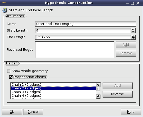
Start and End Length hypothesis allows to divide a geometrical edge into segments so that the first and the last segments have a specified length. The length of medium segments changes with automatically chosen geometric progression.
The direction of the splitting is defined by the orientation of the underlying geometrical edge. Reverse Edges list box allows to specify the edges, for which the splitting should be made in the direction opposing to their orientation. This list box is enabled only if the geometry object is selected for the meshing. In this case it is possible to select edges to be reversed either by directly picking them in the 3D viewer or by selecting the edges or groups of edges in the Object Browser.
Helper group assists you in defining Reversed Edges parameter.
See Also a sample TUI Script of a Defining Start and End Length hypothesis operation.
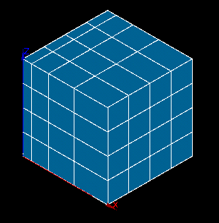
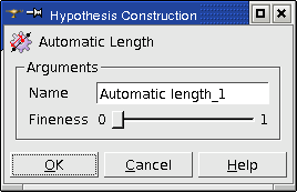
The dialog box prompts you to define the quality of the future mesh by only one parameter, which is Fineness, ranging from 0 (coarse mesh, low number of segments) to 1 (extremely fine mesh, great number of segments).
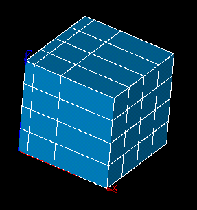
Compare one and the same object (sphere) meshed with minimum and maximum value of this parameter.
Fixed Points hypothesis allows splitting edges through a set of points parametrized on the edge (from 1 to 0) and a number of segments for each interval limited by the points.
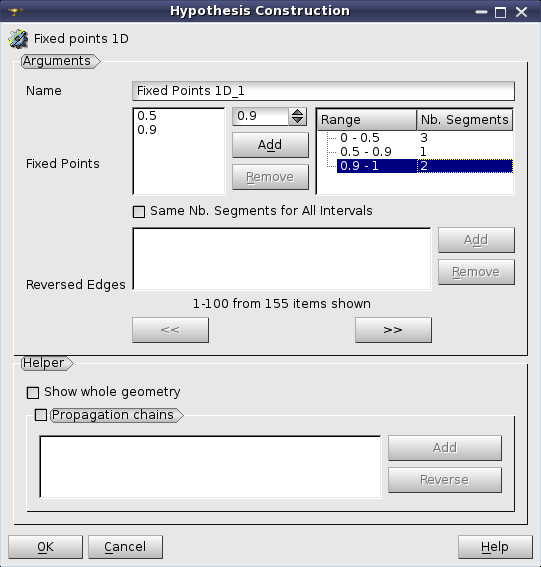
It is possible to check in Same Nb. Segments for all intervals option and to define one value for all intervals.
The splitting direction is defined by the orientation of the underlying geometrical edge. Reverse Edges list box allows to specify the edges for which the splitting should be made in the direction opposite to their orientation. This list box is enabled only if the geometrical object is selected for meshing. In this case it is possible to select the edges to be reversed either directly picking them in the 3D viewer or selecting the edges or groups of edges in the Object Browser.
Helper group assists in defining Reversed Edges parameter.
See Also a sample TUI Script of a Defining Fixed Points hypothesis operation.
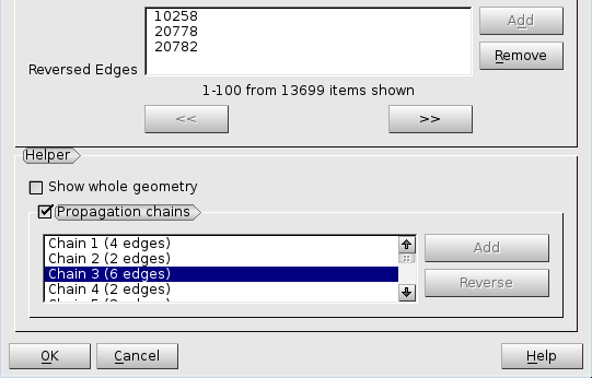
Helper group assists in defining Reversed Edges parameter of the hypotheses depending on edge direction.
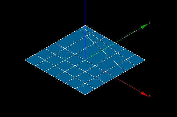
Show whole geometry check-box allows seeing the whole geometrical model in the 3D Viewer, which can help to understand the location of a set of edges within the model.
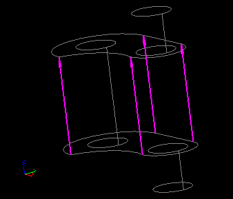
Propagation chains group allows defining Reversed Edges for splitting opposite edges of quadrilateral faces in a logically uniform direction. When this group is activated, the list is filled with propagation chains found within the shape on which a hypothesis is assigned. When a chain is selected in the list its edges are shown in the Viewer with arrows, which enables choosing a common direction for all chain edges. Reverse button inverts the common direction of chain edges. Add button is active if some edges of a chain have a different direction, so you can click Add button to add them to Reversed Edges list.