Version: 8.3.0
To create a mesh on geometry, it is necessary to create a mesh object by choosing
Then you can launch mesh generation by invoking Compute command. The generated mesh will be automatically shown in the Viewer. You can switch off automatic visualization or limit mesh size until which it is automatically shown in Mesh preferences (Automatic update entry).
Mesh generation on the geometry is performed in the bottom-up flow: nodes on vertices are created first, then edges are divided into segments using nodes on vertices; the node of segments are then used to mesh faces; then the nodes of faces are used to mesh solids. This automatically assures the conformity of the mesh.
It is required to choose a meshing algorithm for every dimension of sub-shapes up to the highest dimension to be generated. Note that some algorithms generate elements of several dimensions, and others of only one. It is not necessary to define meshing parameters for all dimensions at once; you can start from 1D meshing parameters only, compute the 1D mesh, then define 2D meshing parameters and compute the 2D mesh (note that 1D mesh will not be re-computed).
An algorithm of a certain dimension chosen at mesh creation is applied to discretize every sub-shape of this dimension. It is possible to specify a different algorithm or hypothesis to be applied to one or a group of sub-shapes by creating a sub-mesh. You can specify no algorithms at all at mesh object creation and specify the meshing parameters on sub-meshes only; then only the sub-shapes, for which an algorithm and a hypothesis (if any) have been defined will be discretized.
Construction of a mesh on a geometry includes at least two (mesh creation and computing) of the following steps:
To construct a mesh:
In the Mesh menu select Create Mesh or click "Create Mesh" button in the toolbar.

"Create Mesh" button
The following dialog box will appear:
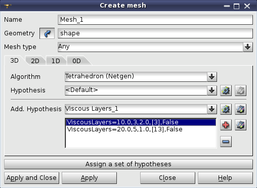
To filter off irrelevant meshing algorithms, you can select Mesh Type in the corresponding list from Any, Hexahedral, Tetrahedral, Triangular and Quadrilateral (there can be less items for the geometry of lower dimensions).
Selection of a mesh type hides all meshing algorithms that cannot generate elements of this type.
Apply meshing algorithms and hypotheses which will be used to compute this mesh.
"Create mesh" dialog box contains several tab pages titled 3D, 2D, 1D and 0D. The title of each page reflects the dimension of the sub-shapes the algorithms listed on this page affect and the maximal dimension of elements the algorithms generate. For example, 3D page lists the algorithms that affect 3D sub-shapes (solids) and generate 3D mesh elements (tetrahedra, hexahedra etc.)
As soon as you have selected an algorithm, you can create a hypothesis (or select an already created one). A set of accessible hypotheses includes only the hypotheses that can be used by the selected algorithm.
For example, you need to mesh a 3D object.
First, you can change a default name of your mesh in the Name box. Then check that the selected geometrical object indicated in Geometry field, is what you wish to mesh; if not, select the correct object in the Object Browser. Click "Select" button near Geometry field if the name of the object has not yet appeared in Geometry field.

"Select" button
Now you can define 3D Algorithm and 3D Hypotheses, which will be applied to discretize the solids of your geometrical object using 3D elements. Click the "Add Hypothesis" button to create and add a hypothesis.

"Add Hypothesis" button
Click the "Plus" button to enable adding more additional hypotheses.
Click the "Edit Hypothesis" button to change the values for the current hypothesis.

"Edit Hypothesis" button
Most 2D and 3D algorithms can work without hypotheses using default meshing parameters. Some algorithms do not require any hypotheses. After selection of an algorithm "Hypothesis" field of the dialog can contain:
After selection of an algorithm Add. Hypothesis field can contain:
Proceed in the same way with 2D and 1D Algorithms and Hypotheses that will be used to mesh faces and edges of your geometry. (Note that any object has edges, even if their existence is not apparent, for example, a sphere has 4 edges). Note that the choice of hypotheses and lower dimension algorithms depends on the higher dimension algorithm.
If you wish you can select other algorithms and/or hypotheses for meshing some sub-shapes of your CAD model by Constructing sub-meshes.
Some algorithms generate mesh of several dimensions, while others produce mesh of only one dimension. In the latter case there must be one Algorithm and zero or several Hypotheses for each dimension of your object, otherwise you will not get any mesh at all. Of course, if you wish to mesh a face, which is a 2D object, you do not need to define a 3D Algorithm and Hypotheses.
In the Object Browser the structure of the new mesh is displayed as follows:
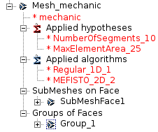
It contains:
There is an alternative way to assign Algorithms and Hypotheses by clicking Assign a set of hypotheses button and selecting among pre-defined sets of algorithms and hypotheses. In addition to the built-in sets of hypotheses, it is possible to create custom sets by editing CustomMeshers.xml file located in the home directory. CustomMeshers.xml file must describe sets of hypotheses in the same way as ${SMESH_ROOT_DIR}/share/salome/resources/smesh/StdMeshers.xml file does (sets of hypotheses are enclosed between <hypotheses-set-group> tags). For example:
If the file contents are incorrect, there can be an error at activation of Mesh module: "fatal parsing error: error
triggered by consumer in line ..."
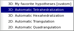
List of sets of hypotheses. Tag [custom] is automatically added to the sets defined by the user.
Consider trying a sample script for construction of a mesh from our TUI Scripts section.
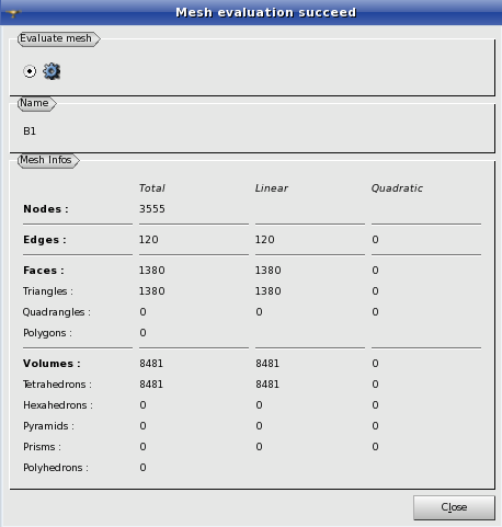
After the mesh object is created and all hypotheses are assigned and before Compute operation, it is possible to calculate the eventual mesh size. For this, select the mesh in the Object Browser and from the Mesh menu select Evaluate. The result of evaluation will be displayed in the following information box:
Before the mesh computation, it is also possible to see the mesh preview. This operation allows to incrementally compute the mesh, dimension by dimension, and to discard an unsatisfactory mesh.
For this, select the mesh in the Object Browser. From the Mesh menu select Preview or click "Preview" button in the toolbar or activate "Preview" item from the pop-up menu.

"Preview" button
Select 1D mesh or 2D mesh preview mode in the Preview dialog.
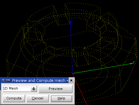

Compute button computes the whole mesh.
When the Preview dialog is closed, the question about the storage of temporarily created mesh elements appears:
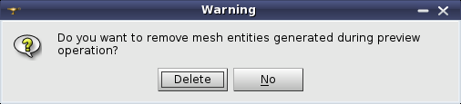
These elements can be kept in the mesh.
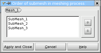
If the mesh contains concurrent sub-meshes, it is possible to change the priority of their computation, i.e. to change the priority of applying algorithms to the shared sub-shapes of the Mesh shape.
To change sub-mesh priority:
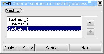
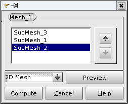
Choose "Change sub-mesh priority" from the Mesh menu or a pop-up menu. The opened dialog shows a list of sub-meshes in the order of their priority.
There is an example of sub-mesh order modifications taking a Mesh created on a Box shape. The main Mesh object:
The first sub-mesh Submesh_1 created on Face_1 is:
The second sub-mesh Submesh_2 created on Face_2 is:
And the last sub-mesh Submesh_3 created on Face_3 is:
The sub-meshes become concurrent if they share sub-shapes that can be meshed with different algorithms (or different hypotheses). In the example, we have three sub-meshes with concurrent algorithms, because they have different hypotheses.
The first mesh computation is made with:
"Mesh order SubMesh_1, SubMesh_2, SubMesh_3"
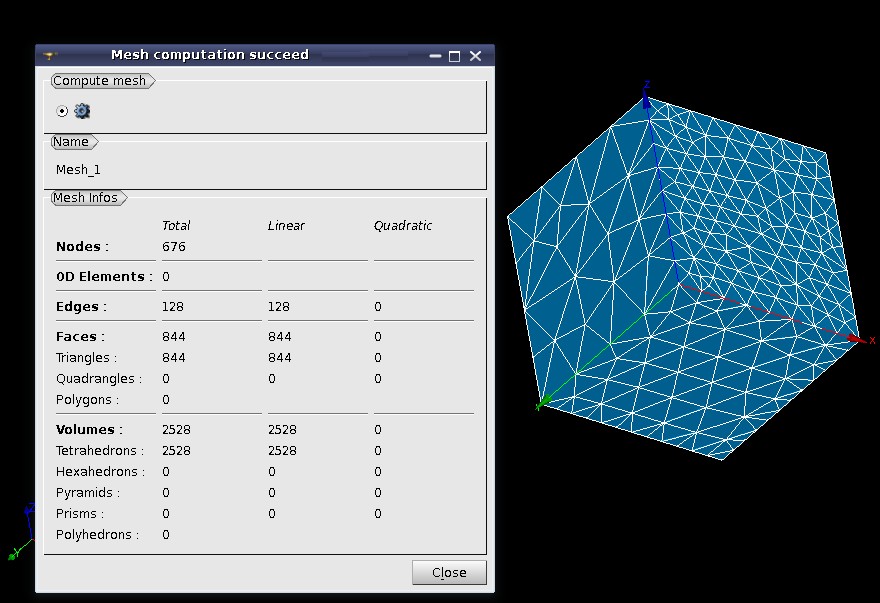
"Result mesh with order SubMesh_1, SubMesh_2, SubMesh_3 "
The next mesh computation is made with:
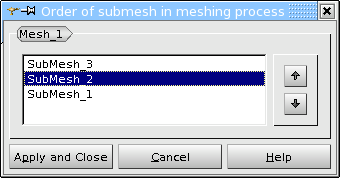
"Mesh order SubMesh_2, SubMesh_1, SubMesh_3"
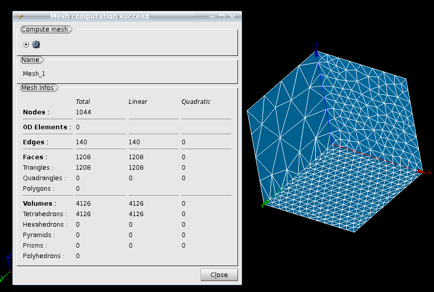
"Result mesh with order SubMesh_2, SubMesh_1, SubMesh_3 "
And the last mesh computation is made with:
"Mesh order SubMesh_3, SubMesh_2, SubMesh_1"
"Result mesh with order SubMesh_3, SubMesh_2, SubMesh_1 "
As we can see, each mesh computation has a different number of result elements and a different mesh discretization on the shared edges (the edges that are shared between Face_1, Face_2 and Face_3)
Additionally, sub-mesh priority (the order of applied algorithms) can be modified not only in a separate dialog box, but also in the Preview. This helps to preview different mesh results, modifying the order of sub-meshes.
"Preview with sub-mesh priority list box"
If there are no concurrent sub-meshes under the Mesh object, the user will see the following information.
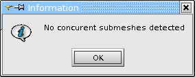
"No concurrent submeshes detected"
It is equally possible to skip the Evaluation and the Preview and to Compute the mesh after the hypotheses are assigned. For this, select your mesh in the Object Browser. From the Mesh menu or the context menu select Compute or click "Compute" button of the toolbar.

"Compute" button
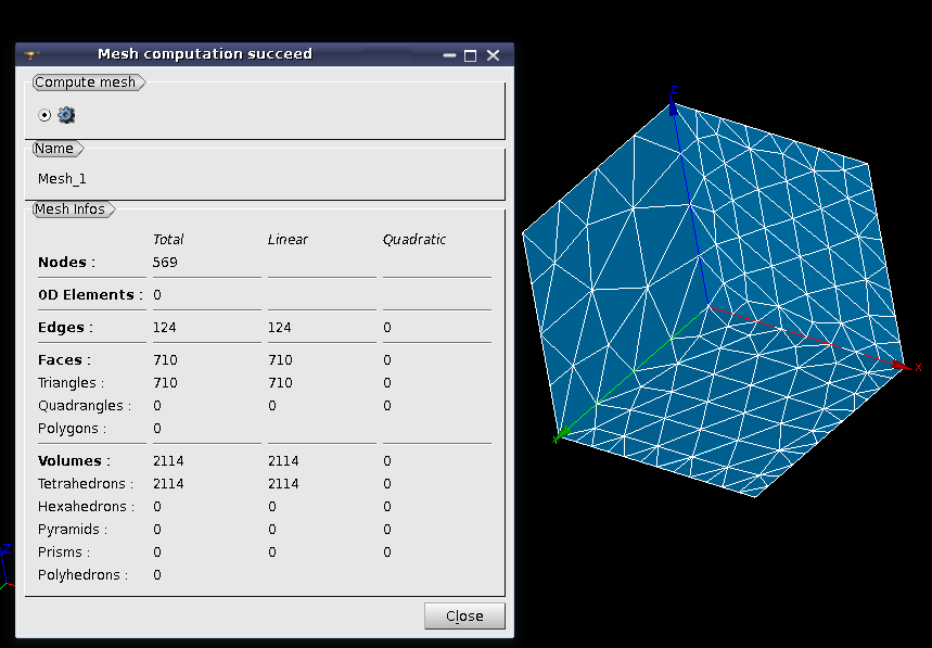
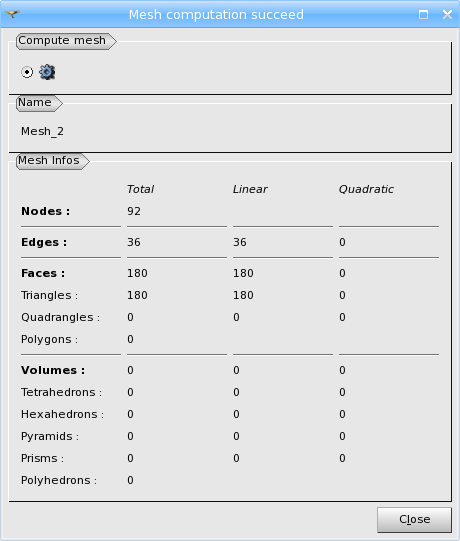
After the mesh computation finishes, the Mesh Computation information box appears. If you close this box and click "Compute" button again, without previously changing meshing parameters, the mesh will NOT be re-computed and the Mesh Computation information box will be shown with the same contents. (To fully re-compute the mesh, invoke Clear Mesh Data command before).
If the mesh computation has been a success, the box shows information on the number of entities of different types in the mesh.
If the mesh computation has failed, the information about the cause of the failure is provided in Errors table.
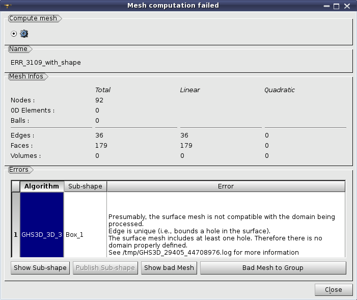
After you select an error in Errors table, Show Sub-shape button allows visualizing in magenta the geometrical entity meshing of which failed (Name of this entity or its ID and type is shown in Sub-shape column).
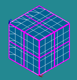
3D algorithm failed to compute mesh on a box shown using Show Sub-shape button
Publish Sub-shape button publishes the sub-shape, whose meshing has failed, in the Geometry component as a child of the main shape, which allows analyzing the problematic geometry and creating a sub-mesh on it in order to locally tune the hypotheses.
If the failure is caused by an invalid input mesh and the algorithm has found which mesh entities are bad, Show bad Mesh button appears in the dialog. Clicked, it shows the bad mesh entities in the Viewer in magenta. Sometimes the shown mesh entities are too small or/and hidden by other mesh elements. They can be seen after switching the mesh to Wireframe visualization mode or switching off the visualization of faces and volumes (if any).
Bad Mesh to Group button creates groups of bad mesh entities to facilitate their analysis.
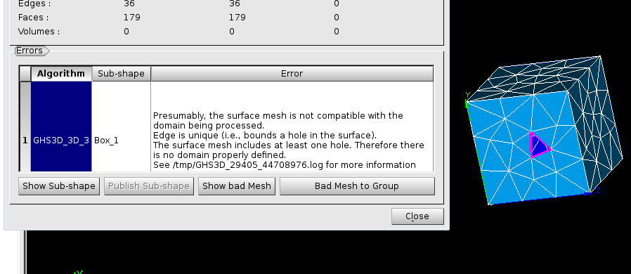
Edges bounding a hole in the surface are shown in magenta using Show bad Mesh button
It is possible to edit the mesh of a lower dimension before generation of the mesh of a higher dimension.
For example you can generate a 2D mesh, modify it using e.g. Pattern mapping, and then generate a 3D mesh basing on the modified 2D mesh. The workflow is as follows:
See Also a sample TUI Script demonstrates the possibility of Intermediate edition while meshing

