Revolution is used to build mesh elements of plus one dimension than the input ones. Boundary elements around generated mesh of plus one dimension are additionally created. All created elements can be automatically grouped. Revolution can be used to create a structured mesh from scratch. See Extrusion page for general information on Revolution, which can be viewed as extrusion along a circular path.
To apply revolution:
-
From the Modification menu choose the Revolution item or click "Revolution" button in the toolbar.
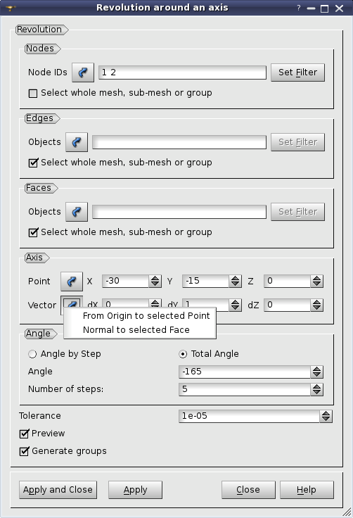
"Revolution" buttonThe following dialog will appear:
-
In this dialog:
-
Use Selection button to specify what you are going to select at a given moment, Nodes, Edges or Faces.
"Selection" button
-
Specify Nodes, Edges and Faces, which will be revolved, by one of following means:
-
Select the whole mesh, sub-mesh or group activating this check-box.
-
Choose mesh elements with the mouse in the 3D Viewer. It is possible to select a whole area with a mouse frame.
-
Input the element IDs directly in Node IDs, Edge IDs and Face IDs fields. The selected elements will be highlighted in the viewer, if the mesh is shown there.
-
Apply Filters. Set filter button allows to apply a filter to the selection of elements. See more about filters in the Selection filters page.
-
Specify the Axis of revolution:
-
Specify the coordinates of the start Point of the axis of revolution; either directly or by picking a node in the Viewer (selection of nodes is activated as you click the Selection button).
-
Specify the Vector of the axis in either of three ways:
-
directly adjust vector components;
-
click Selection button, choose From Origin to selected Point in the opened menu and pick a node in the Viewer;
-
click Selection button, chose Normal to selected Face in the opened menu and pick a mesh face in the Viewer.
-
Specify the Angle of revolution and the Number of steps of revolution,
-
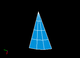
Angle by Step - the elements are revolved by the specified angle at each step (i.e. for Angle=30 and Number of Steps=3, the elements will be extruded by 30 degrees twice for a total of 30*3=90)
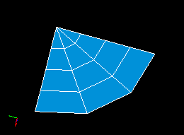
Example of Revolution with Angle by Step. Angle=30 and Number of Steps=3
-
Total Angle - the elements are revolved by the specified angle only once and the number of steps defines the number of iterations (i.e. for Angle=30 and Number of Steps=3, the elements will be revolved by 30/3=10 degrees twice for a total of 30).
Example of Revolution with Total Angle. Angle=30 and Number of Steps=3
-
Specify the Tolerance, which is used to detect nodes lying on the axis of revolution.
-
Activate Preview check-box to see the result mesh in the viewer.
-
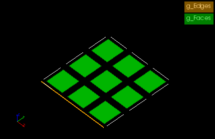
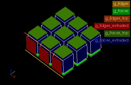
If you activate Generate Groups check-box, the result elements created from selected elements contained in groups will be included into new groups named by pattern "<old group
name>_rotated" and "<old group name>_top". For example if a selected quadrangle is included in g_Faces group (see figures below) then result hexahedra will be included in g_Faces_rotated group and a quadrangle created at the "top" of revolved mesh will be included in g_Faces_top group.
This check-box is active only if there are some groups in the mesh.
-
Click Apply or Apply and Close button to confirm the operation.
See Also a sample TUI Script of a Revolution operation.