Tutorials
This tutorial aims at giving important steps of the use of « Bloc Fissure ». Those steps are the standard procedure that the user should apply to avoid « Bloc Fissure » failure and unexpected problem in the modelisation afterwards.
First, the user should ask himself if its case is compatible with « Bloc Fissure ». See the section on limitations.
- Convert elements from quadratic to linear
Mesh Module: Modification > Convert to/from quadratic
- Change the orientation of all faces to set them to outgoing
Mesh Module: Modification > Reorient faces
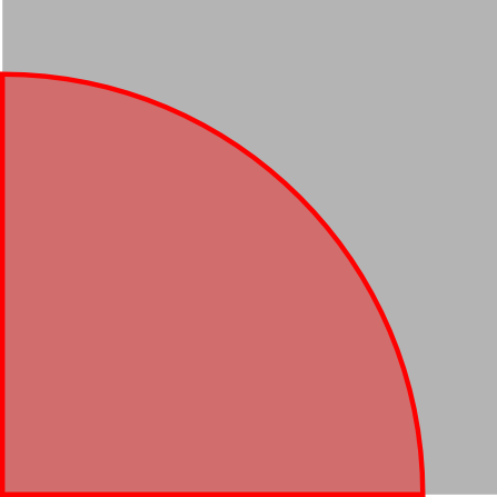
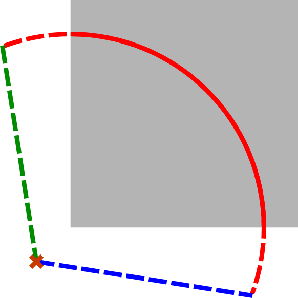
- Verify that the crack exceeds everywhere from the structure. If it’s not the case, move or extend the crack geometry.
- Verify that the crack front edges don’t stop right at the Box surface.
Here are some advices :
To move the crack:
GEOM Module: Operations > Transformation > Translation
- First way to extend the crack geometry in GEOM module:
- Operations > Explode: Choose the crack geometry and explode into Edges
- Operation > Transformations > Extension: extend the length of the crack edges
- Rebuild edges to get a closed group of edges exceeding from the structure
- New Entity > Build > Wire: Create a wire from the edges
- New Entity > Build > Face: Create a face from the wire
- Get the new crack front edge number
|

|
|

|
| Initial bad crack geometry | Explode face into edges | Extend front edge and rebuild wire | Rebuild crack face |
- second way to extend the crack geometry in GEOM module:
- Create new surfaces linked to the original crack geometry
- Fuse the surfaces to get an extended crack
- Execute the « Bloc Fissure » script and check that it ended successfully.
- Reorient faces to outgoing normal
- Rebuild groups impacted by crack insertion
- Export the cracked mesh