This operation allows fixing the orientation of a set of faces in the following ways:
-
The required orientation of a set of neighboring faces can be defined by a vector giving the direction of a normal to a certain face.
Since the direction of face normals in the set can be even opposite, it is necessary to specify a control face, the normal to which will be compared with the vector. This face can be either:
-
found by proximity to a given point, or
-
specified explicitly.
-
Alternatively, the faces can be oriented relatively to the adjacent volumes.
The orientation of a face is changed by reverting the order of its nodes.
To set orientation of faces:
-
In the Modification menu select Reorient faces item or click Reorient faces button in the toolbar.
"Reorient faces" button
-
In the "Reorient faces" dialog box
-
Select the Object (mesh, sub-mesh or group) containing faces to reorient, in the Object Browser or in the 3D Viewer.
-
To reorient by direction of the face normal:
-
Specify the coordinates of the Point by which the control face will be found. You can specify the Point by picking a node in the 3D Viewer or selecting a vertex in the Object Browser.
-
Set up the Direction vector to be compared with the normal of the control face. There are following options:
-
adjust vector components directly;
-
select a vertex in the Object Browser or a node in the 3D Viewer; their coordinates will define vector components;
-
pick two nodes (holding Shift button), the Direction vector will go from the first to the second node.
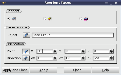
The orientation of adjacent faces is chosen according to a vector. The control face is found by point.
-
In the second mode it is possible to pick the Face by mouse in the 3D Viewer or directly input the Face ID in the corresponding field.
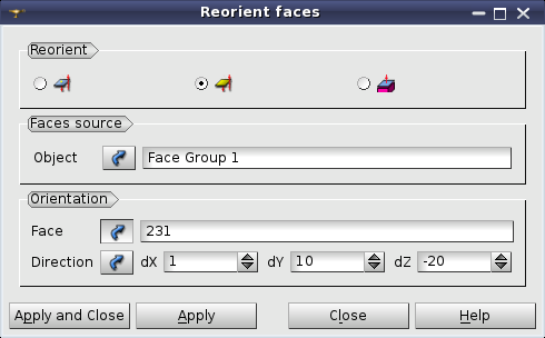
The orientation of adjacent faces is chosen according to a vector. The control face is explicitly given.
-
In the third mode, the faces can be reoriented according to volumes:
-
Select an object (mesh, sub-mesh or group) containing reference Volumes, in the Object Browser or in the 3D Viewer.
-
Specify whether face normals should point outside or inside the reference volumes using Face normal outside volume check-box.
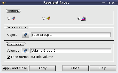
The orientation of faces is chosen relatively to adjacent volumes.
-
Click the Apply or Apply and Close button to confirm the operation.
See Also a sample TUI Script of a Reorient faces operation.


