Introduction
General presentation
The software HOMARD is intended to adapt the meshes within the framework of the computer codes by finite elements or finite volumes. This software, carried out by EDF R&D, proceeds by refinement and unrefinement of the two-dimensional or three-dimensional meshes. It is conceived to be used independently of the computer code with which it is coupled.
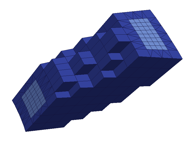
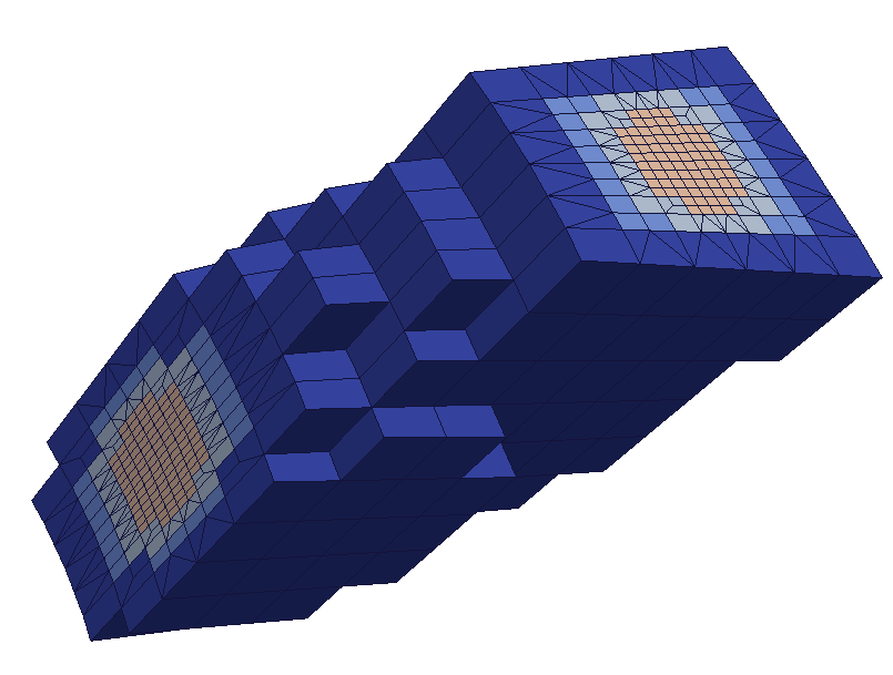
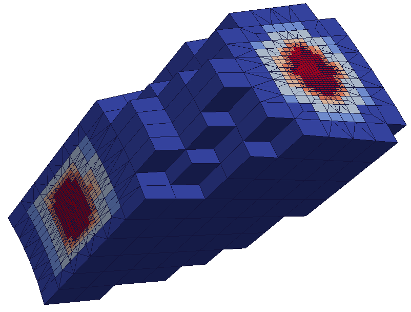
To refine the mesh means to cut out elements indicated according to indications provided by the user. Unrefine the mesh means to reconsider behind cuttings previously carried out: thus, to in no case HOMARD cannot simplify an existing mesh which will have been created too fine. Unrefinement takes all its importance in calculations when the zone of interest moves during calculation: one will not hold any more account of refinements previously carried out and which become useless. One will find of it an illustration with the bottom of this page.
- HOMARD can treat meshes into 2 or 3 dimensions and comprising the following elements:
- mesh-points
- segments
- triangles
- quadrangles
- tetrahedra
- hexahedra
- prisms
These elements can be present simultaneously. For example, HOMARD will be able to adapt a comprising mesh of the triangles and the quadrangles. The accepted nodes are obviously the nodes which are the vertices of the elements, which corresponds to a traditional description “in degree 1”. If the elements are described “in degree 2”, the additional nodes are managed. On the other hand, elements described in degree 1 and others described in degree 2 cannot be inthe same mesh. Lastly, HOMARD can take into account isolated nodes, which would not belong to any definition of elements: they will arise such as they are from the process of adaptation.
The case of the pyramids is except for. For a comprising mesh of the hexahedrons or the prisms, the setting in conformity of the mesh resulting from refinement creates pyramids to ensure the connection between two areas of different levels of refinement. These pyramids are managed like all the elements of transition and are no more split thereafter. On the other hand, if the initial mesh contains pyramids, HOMARD will not be able to adapt it and will transmit an error message. In certain typical cases, one will be able nevertheless to treat such a mesh, as it is described in the heading advanced options of the creation of a case.
Several motivations appear to adapt a mesh:
- one wants to simplify the realization of the mesh of a complex geometry: one starts from a coarse mesh and one entrusts to an automatic process the load to refine it.
- one wants to make sure of the convergence of the numerical solution: rather than to realize with the hand of the increasingly fine meshs, one lets the software seek itself the places where it would be necessary to refine the mesh to increase the precision of the result.
- the conditions of calculation change during time: the zones which must be with a mesh finely move. If the mesh is fine everywhere as of the beginning, the mesh is too large. While adapting progressively, the mesh will be fine only at the places necessary: its size will be reduced and the quality of the solution will be good.
In all the cases, the principle of the adaptation of mesh remains the same one. On the starting mesh, one carries out standard calculation. With an analysis of the numerical solution obtained, one estimates the error which was made compared to the real solution. This estimate is represented by a value of indicator of error in each element of calculation. From there, the following principle is applied: the elements where the indicator of error is strong should be smaller and, reciprocally, the elements where the indicator of error is low could be larger. With this information, one feeds HOMARD which will modify the mesh consequently. On the new mesh, calculation then will be started again.
Broadly speaking, an iteration for meshing adaptation is as shown on the figure below. The finite element software calculates the numerical solution on meshing Mk, then, from that, deduces the values for the error indicator over the whole meshing. Based on the knowledge of meshing #k and indicator #k, HOMARD generates a new meshing #k+1.

The complete chain starts from the initial meshing, then incorporates successive links (calculation of indicator / adaptation).

Some variations may exist. If no error indicator is available, another field can be used to drive the adaptation. A stress field in mechanics can be used: the refinement of the elements where the stress is high is often efficient to improve the quality of the results. It is also possible to drive the adaptation according the variation of a field from one element to its neighbours. The refinement can be filtered by zones or groups of elements.
Note
For a extensive description of HOMARD, see Description of HOMARD.
Note
To quote HOMARD, please refer to:
Gérald Nicolas, Thierry Fouquet, Samuel Geniaut, Sam Cuvilliez, Improved adaptive mesh refinement for conformal hexahedral meshes, “Advances in Engineering Software”, Vol. 102, pp. 14-28, 2016, doi:10.1016/j.advengsoft.2016.07.014
- Nicolas and T. Fouquet, Adaptive Mesh Refinement for Conformal Hexahedral Meshes, “Finite Elements in Analysis and Design”, Vol. 67, pp. 1-12, 2013, doi:10.1016/j.finel.2012.11.008
Note
This alternation (computation/adaptation) suits in the YACS schemes.
Methods for splitting the elements
All in all, the process of meshing adaptation by splitting element is a two-tier process. First, all element specified by the error indicator are split. The resulting meshing is uncorrect : nodes are pending at the junction between areas to be refined, and an area to be retained. The second stage aims at solving all of these conformity problems.
There are different splitting methods for the two phases. During the first phase, all of the element are split in the same manner ; this is the so-called standard splitting. During the second phase, some of the meshing conformity conflicts in the junction area are settled by the same standard splitting of element, while others are settled by special splitting.
The various splitting modes have been choosen to preserve the mesh quality, all along the adaptive process.
Standard splitting
Standard element splitting is carried out with a view to restricting the number of cases. Thus, edges are split into two equal sections.
To split a triangle, the three edges are split into two sections each, thus producing four similar triangles. They retain the same quality.

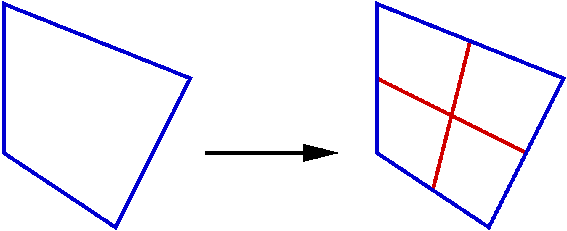
To split a quadrangle, the four edges are split into two sections each, thus producing four non-similar quadrangles with different quality.
Tetrahedrons are split in eight. First, each of the triangular faces is split into 4 similar triangular faces.
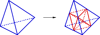
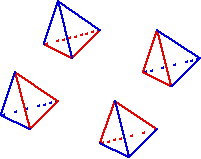
Face splitting produces four tetrahedrons at the angles of the initial tetrahedron. It should be noted that the four new tetrahedrons are homothetic to the initial tetrahedron. Therefore, they retain the same qualities.
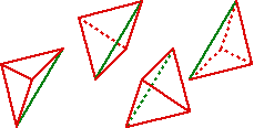
At the core of the tetrahedron, there remains a block shaped like two pyramids joined at their bases. An edge is generated using one of the three possible diagonals, then the four faces containing the edge, and two external edges.

This, in turn, creates 4 new tetrahedrons. It should be noted that they are similar two by two but that they can never be similar to the initial tetrahedron. They can therefore never have the same quality as the initial tetrahedron. However, different results are obtained, depending on the diagonal selected for splitting the internal pyramidal block. Where quality is concerned, it is always best to select the smallest of the three possible diagonals.
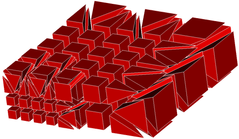
Hexaedrons are split in eight. Each of the quadrangular faces is split into 4 quadrangular faces. Edges are created connecting each centre of opposite faces. This generates a new point located at the centre of the hexahedron.

Pentaedrons are split in eight. Each of the quadrangular faces is split into 4 quadrangular faces and the two triangles are split into 4. Edges are created connecting each centre of quadrangular faces. Those 3 edges create 4 triangles at the centre of the pentaedron. Six quandrangular faces are created to complete the construction of the height pentaedrons.

Splitting for the conformity
Splitting for conformity is applicable to the elements at the interface between two different levels of refinement. Such splitting may produce element of lower quality compared to the initial element, and in the general algorithm, one sees how this drawback is reckoned with to reduce its consequences.
For triangles, one of the three edges is split in two. Its middle is joined to the opposite vertex to form two additional triangles.

For quadrangles, three configurations exist. First, one of the four edges is split in two. Its middle is joined to the opposite vertex to form three triangles. The mesh obtained is then mixed.

For a quadrangle where two opposite edges are cut, the two middle points are connected. Two quadrangles are created.

For a quadrangle where two opposite edges are cut, a new vertex is created at the centre of the quadrangle. This center point is then connected to the two middle points are connected and to the opposite vertex. Three quadrangles are created.

For a tetrahedron with three split edges, this is possible only if the edges are concurrent. Therefore, one of the four faces is split in four. The middles of the split edges are joined to the opposite vertexes. The three other faces are thus split in two, and four tetrahedrons are created.
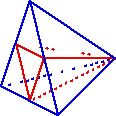
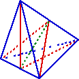
For a tetrahedron with two split edges, this is possible only if the edges are opposite. All the middles of these edges are joined to the other apexes, as well as the edge middles. The four faces are split in two, and four tetrahedrons are created.
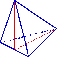
For a tetrahedron with one split edge, the middle of the split edge is joined to the opposite apex, and two tetrahedrons are created.
The conformal strategy for the hexahedrons is based on tetrahedrons and pyramids. The situation depends on the number of non conformities, following the rules for the quadrangles. Here is some examples from the 66 possible situations.
For an hexahedron with one face cut, we create 4 edges, 4 tetrahedrons and 5 pyramids.

For an hexahedron with only one edge cut, we create deux internal edges and four pyramids.

For an hexahedron with two edges cut, we create one central point 10 edges, 12 tetrahedrons and 2 pyramids.

For an hexahedron with three edges cut, we create one central point, 11 edges and 18 tetrahedrons.

Algorithm
The strategy adopted for the algorithm in HOMARD consists in forcing splitting in four for all faces with two hanging nodes. Eventually, only the faces with non conformity points are faces where one and only edge is split. The simplest possible solution is thus used for conformity as seen before. The latter stage of conformity introduces element of modified quality compared to that of the element it originated from. This drawback remains under control as we have chosen to grant a temporary status to the conformity element: they exist to produce a meshing acceptable by the calculation softwares, but they disappear if they are required to be further split. As a consequence, quality loss does not propagate along iterations of meshing adaptation, and remains restricted in value as well as in number of element concerned.
The algorithm is:
- Transfer of refining or coarsening indications over element into decisions to split or group edges, triangles and quadrangles.
- Removal of temporary compliance element.
- By considering all triangles and quadrangles from the lowest splitting level to the highest splitting level, conflict solving on refining using the basic rules.
- By considering all triangles and quadrangles from the lowest splitting level to the highest splitting level, conflict solving on coarsening using the basic rules.
- Effective generation of new meshing : standard splitting, compliance tracking.
