Settings
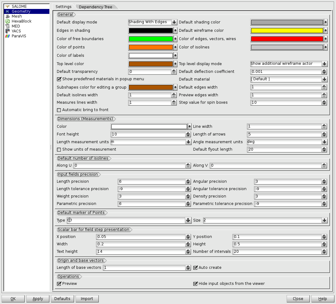
In the Geometry module you can set preferences for visualization of geometrical figures, which can be used right now or in later sessions with this module according to the preferences.
- To redefine any color click on the corresponding line to access to the Select Color dialog box.
-
Dimensions (Measurements) - a group of preferences controlling the presentation of dimensions.
-
Color - allows to define color for persistent dimension presentations.
-
Line width - allows to define pixel width of dimension lines.
-
Font height - allows to define height of dimension text.
-
Length of arrows - allows to define length of dimension arrows.
-
Length measurement units - allows to define units of measurement for lengths dimensions.
-
Angle measurement units - allows to define units of measurement for angles dimensions.
-
Show units of measurements - when this option is on, the measurement units are added as prefix to value label of dimension.
-
Default flyout length - allows to define default flyout length used when creating the dimensions. The length can be interactively changed after creation by moving the flyouts.
-
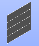
Default number of isolines - allows to specify the default number of isolines along Along U and Along V coordinate axes. They are shown on each selected face. For example:
This preference is not related with Create Isoline operation. By default Along U and Along V are null and isolines are not drawn.
-
Input fields precision - a group of preferences controlling input precision for floating-point data. The semantics of the precision values is described in detail in Using input widgets chapter of GUI documentation (Introduction to Salome Platform / Introduction to GUI / Using input widgets). In brief: positive precision value is the maximum allowed number of digits after the decimal point in the fixed-point format; nagative precision value is the maximum allowed number of significant digits in mantissa in either the fixed-point or scientific format.
-
Length precision - allows to adjust input precision of coordinates and dimensions.
-
Angular precision - allows to adjust input precision of angles.
-
Length tolerance precision - allows to adjust input precision of tolerance of coordinates and dimensions.
-
Angular tolerance precision - allows to adjust input precision of tolerance of angles.
-
Weight precision - allows to adjust input precision of weight and mass.
-
Density precision - allows to a just input precision of density.
-
Parametric precision - allows to adjust input precision of parametric values.
-
Parametric tolerance precision - allows to adjust input precision of tolerance in parametric space.
-
Default marker of points
-
Type - allows to select the default symbol for representation of points (cross, asterisk, etc.).
-
Size - allows to define the default size of the marker from 1 (smallest) to 7 (largest).
-
Scalar bar for field presentation
-
X position - allows to define the parametric X position of the scalar bar.
-
Y position - allows to define the parametric Y position of the scalar bar.
-
Width - allows to define the parametric width of the scalar bar.
-
Height - allows to define the parametric height of the scalar bar.
-
Text height - allows to define the font height of the scalar bar labels.
-
Number of intervals - allows to define the number of scalar bar intervals.
-
Origin and base vectors
-
Length of base vectors - allows to define the length of base vectors.
-
Auto create - allows to automatically create a point of origin and three base vectors of the rectangular coordinate system immediately after the module activation.
-
Operations
-
Preview - allows to customize the displaying preview by default.
-
Hide input objects from the viewer - allows automatic hiding of input shapes from the 3D viewer (OCC and VTK) in all operations of Geometry module.
Dependency Tree
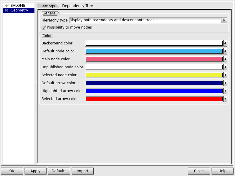
This tab groups preferences for visualization of Dependency Tree in the 2D Viewer.
-
General
-
Hierarchy type - allows to choose the default display mode of the dependency tree.
-
Possibility to move nodes - enables/disables the possibility of moving nodes by default.
-
Color
-
Background color - allows to select the default background color.
-
Default node color - allows to select the default node color.
-
Main node color - allows to select the default main node color.
-
Unpublished node color - allows to select the default node color for unpublished objects.
-
Selected node color - allows to select the default selected node color.
-
Default arrow color - allows to select the default arrow color.
-
Highlighted arrow color - allows to select the default highlighted arrow color.
-
Selected arrow color - allows to select the default selected arrow color.


